Hi Cadet community,
I’m trying to learn to use CADET. I checked the example - CADET Introduction in Getting started. So far, I understood why certain things should be executed.
Next, I checked CADET Tutorial. The example 01_generating_flow_demonstration is not so hard to understand.
The first two exercises in 02_generating_flow_exercises were not so hard too.
However, I am getting confused with the bonus exercises where multiple inlets were introduced. Let me refer to the first bonus.
model = create_dynflow_template(n_comp=2)

model.root.input.solver.sections.nsec = 2
model.root.input.solver.sections.section_times = [0.0, 1.0, 2.0] # min
model.root.input.solver.sections.section_continuity = [0, 0]

model.root.input.model.unit_000.sec_000.const_coeff = [0.0, 0.5]    # mol / m^3
model.root.input.model.unit_001.sec_000.const_coeff = [2.0, 1.0]    # mol / m^3

model.root.input.solver.user_solution_times = np.linspace(0, 2.0, 1001)

model.root.input.model.connections.nswitches = 2
model.root.input.model.connections.switch_000.section = 0
model.root.input.model.connections.switch_000.connections = [
    0, 2, -1, -1, 1,
    1, 2, -1, -1, 0,
]

model.root.input.model.connections.switch_001.section = 1
model.root.input.model.connections.switch_001.connections = [
    0, 2, -1, -1, 0,
    1, 2, -1, -1, 1,
]

run_simulation(model)
plot_dynflow_results(model)
Here, the const_coeff for two components are [0.0, 0.5]. So basically, the concentration of the first component in section 1 is zero, while 0.5 for the second component.
So I played around with the flow rate of the first section, specifically, this piece of command below:
model.root.input.model.connections.switch_000.connections = [
    0, 2, -1, -1, 1,
    1, 2, -1, -1, 0,
]
Because the concentration of the first component is zero, it doesn’t matter if the flow rate is zero or not.
-
Why the flow rate
Q0of second component is 0, but we still have the inlet for it in the first section? The same for the second section. Why the flow rateQ0of first component is 0, but we still have the inlet for it in the second section? -
If I use the setting below (in tutorial), I get this concentration profile.
model.root.input.model.connections.switch_000.connections = [
    0, 2, -1, -1, 1,
    1, 2, -1, -1, 0,
]
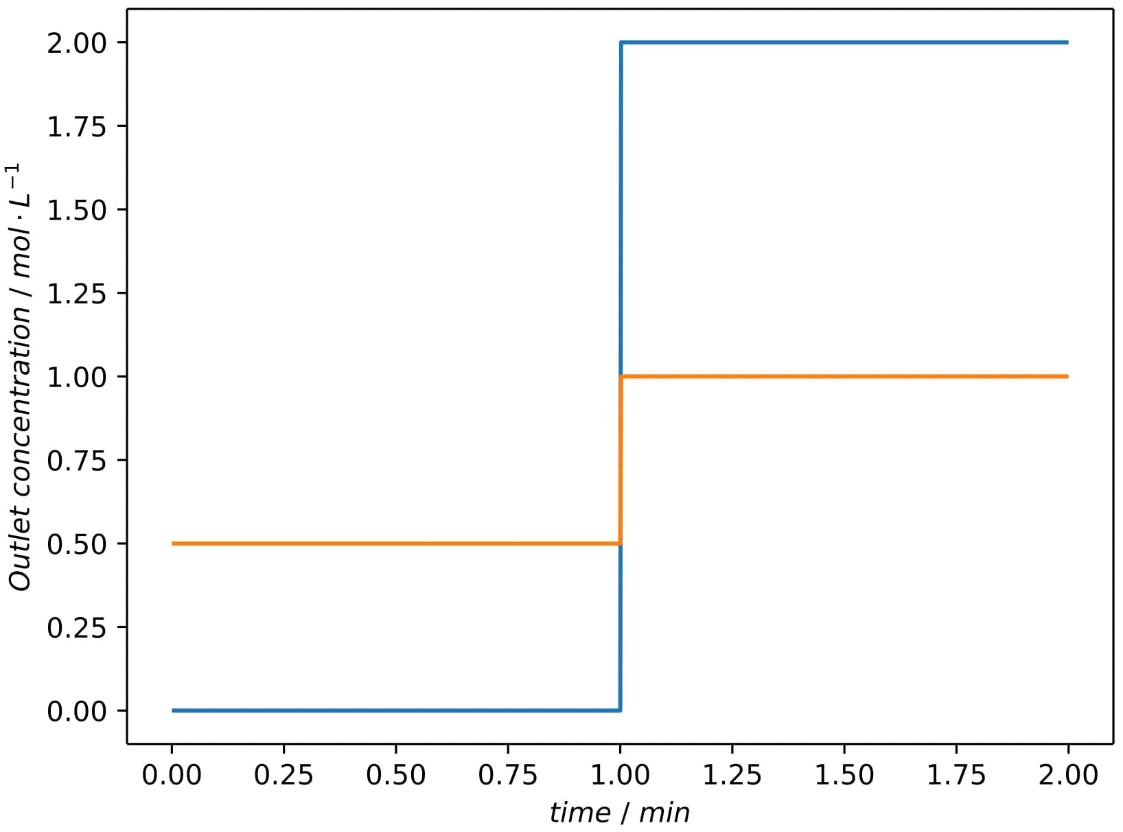
However, if I change Q0 of the second component to 1, I got the concentration profile below.
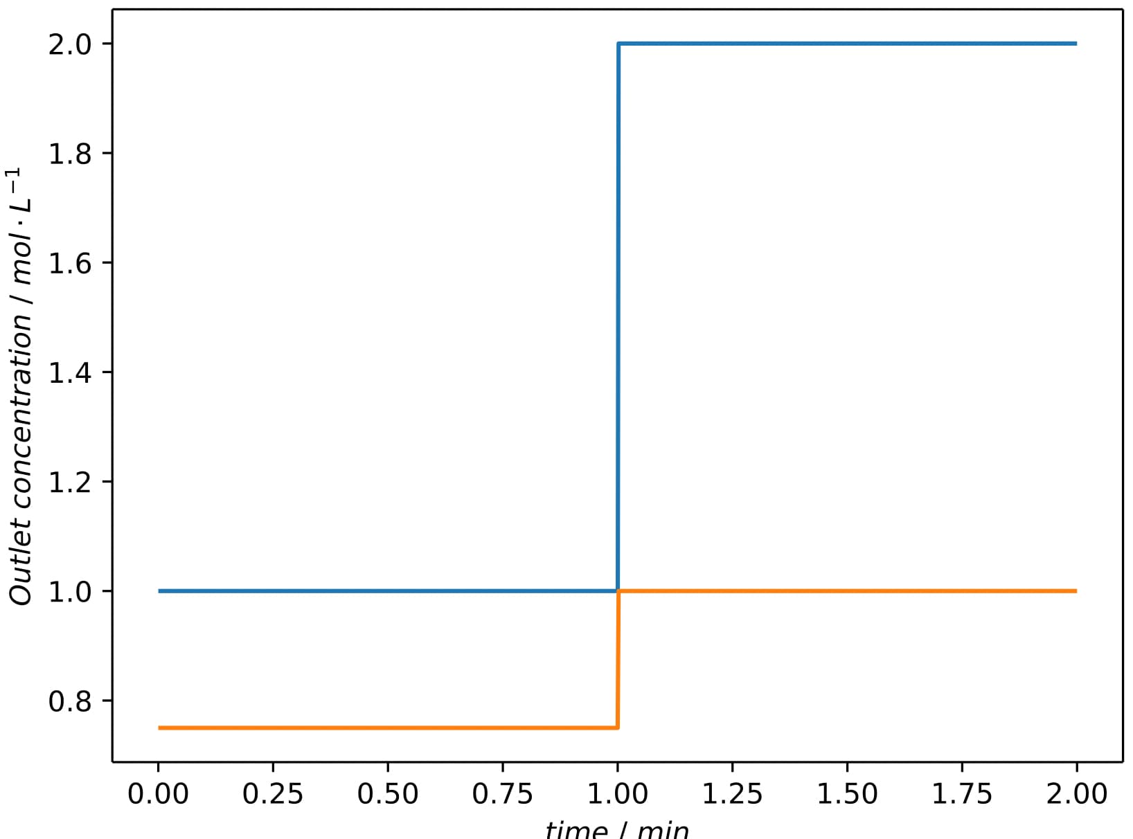
Now the concentration of the first component in the section 1 starts at 1, while ~ 0.7 for second component. This is where I don’t understand.
For the second bonus exercise, I have a few questions.
model = create_dynflow_template(n_comp=1, enable_dynflow=True)

model.root.input.solver.sections.nsec = 3
model.root.input.solver.sections.section_times = [0.0, 1.0, 2.0, 3.0] # min
model.root.input.solver.sections.section_continuity = [0, 0, 0]

model.root.input.model.unit_000.sec_000.const_coeff = [0]    # mol / m^3
model.root.input.model.unit_001.sec_000.const_coeff = [1]    # mol / m^3

model.root.input.solver.user_solution_times = np.linspace(0, 3.0, 1001)

model.root.input.model.connections.nswitches = 3
model.root.input.model.connections.switch_000.section = 0
model.root.input.model.connections.switch_000.connections = [
    0, 2, -1, -1, 1, -1, 0, 0,
    1, 2, -1, -1, 0, 1.0, 0, 0,
]

model.root.input.model.connections.switch_001.section = 1
model.root.input.model.connections.switch_001.connections = [
    1, 2, -1, -1, 1, -1, 0, 0,
]

model.root.input.model.connections.switch_002.section = 2
model.root.input.model.connections.switch_002.connections = [
    0, 2, -1, -1, 0, 1, 0, 0,
    1, 2, -1, -1, 1.0, -1.0, 0, 0,
]

run_simulation(model)
plot_dynflow_results(model)
-
We have only two units representing as inlet, and one unit as outlet. Why do have three switches? Where is the third switch (valve)?
-
The concentration of the first component is declared zero here
model.root.input.model.unit_000.sec_000.const_coeff = [0] # mol / m^3
Why do we still have the concentration profile for it? -
It seems to me the way we declare the concentration
p_i( t )bymodel.root.input.model.unit_001.sec_000.const_coeff = [1] # mol / m^3
or Q by model.root.input.model.connections.switch_001.connections
could be used to manipulate the inlet profile. I could manually calculate the inlet profile for the former aka the specification of network connection is in short format, including 5 columns.
However, I can’t comprehend how the inlet concentration could be constructed if the long format is used aka
[UnitOpID from, UnitOpID to, Component from, Component to, volumetric flow rate, linear flow rate coefficient, quadratic flow rate coefficient, cubic flow rate coefficient]
Could anyone tell me if they are actually different and how we could manually verify for the latter?
Thank you so much for your time.