Hello CADET Developers,
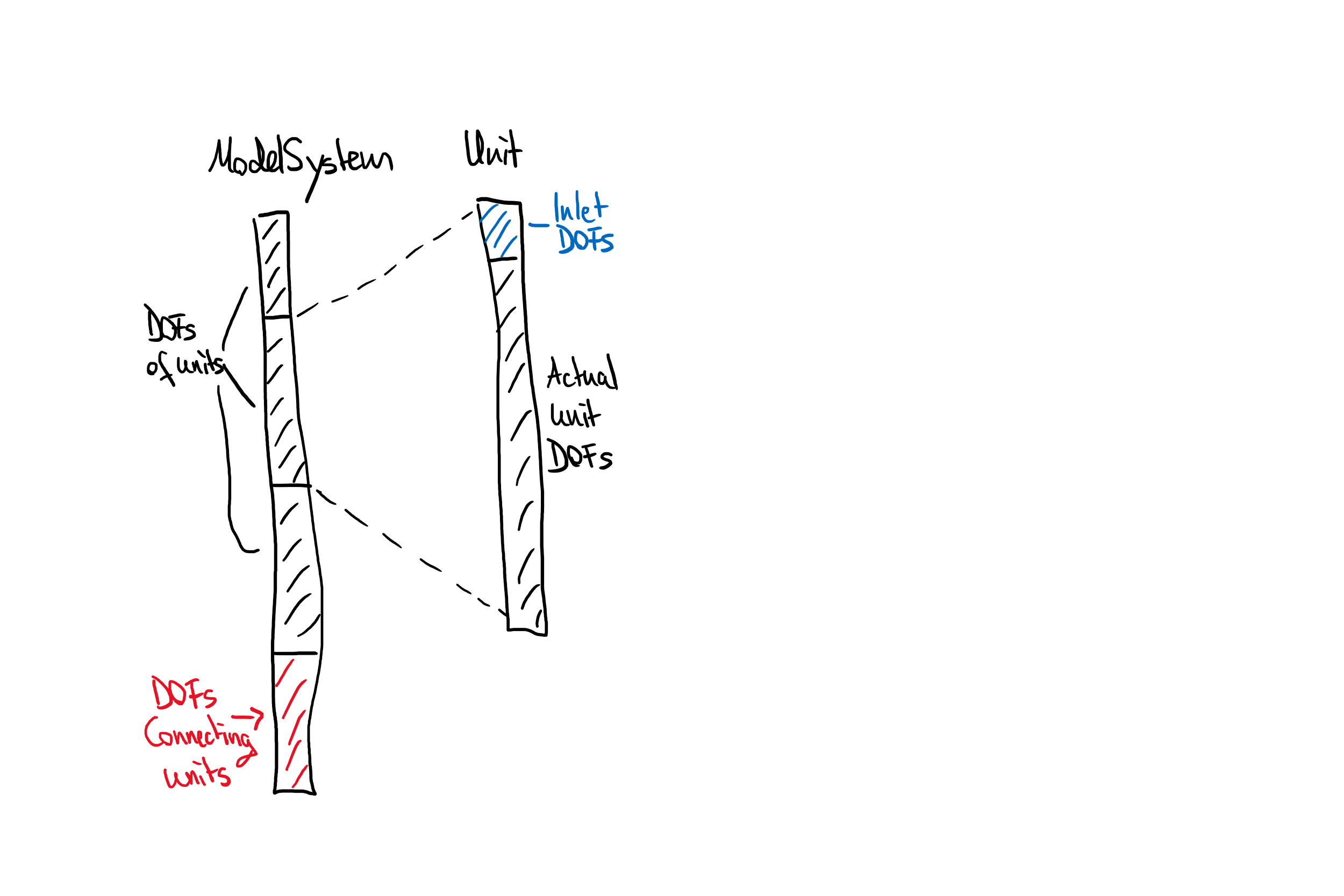
I am trying to understand how the global_last_state_vector_y is defined and stored in CADET, in order to slice the “last_state” vector corresponding to each unit operation.
According to CADET documentation, the length of LAST_STATE_Y is equal to NDOF (number of degrees of freedom)/2NDOF and NDOF is defined as follows:
NDOF = Column bulk DOFs: nCol * nComp + Particle DOFs: nCol * nParType particles each having nComp (liquid phase) + sum boundStates (solid phase) DOFs in each shell; there are nParCell shells for each particle type + Flux DOFs: nCol * nComp * nParType (as many as column bulk DOFs) + Inlet DOFs: nComp
So, for example if I have a single component system, which is modelled with 75 axial (NCOL) and 20 radial (nParType) cells, then using the above formula results in NDOF = 3151 but when I checked the length of LAST_STATE_Y in CADET output file then it was equal to 3155. It means there are 4 extra terms, then I further looked into the source code and in ModelSymtemImpl.cpp a following function related to calculation of NDOF is defined as:
unsigned int ModelSystem::numDofs() const CADET_NOEXCEPT
{
	return _dofOffset.back() + numCouplingDOF();
}
One of the term in the return argument of this function is numCouplingDOF() and I am not sure what information this term carries and maybe these are the missing 4 terms I am not able to calculate. Can anyone please help me out in understanding how these terms are stored in the global last_state vector so that I can identify them for each unit operation?