Dimensionality of various outputs

Johannes, Jazib and I were just discussing the dll interface for CADET and the various outputs. The documentation for solution_bulk, solution_particle, solution_solid etc. is just ntime x UNITOPORDERING but that does not seem to be defined anywhere. I don’t think all of these have the same dimensionality for all unit operations.

I think we need documentation for each unit operation to define the output dimensions of all the outputs. Not only would it help the interface it would also help people that have to use any of those fields.

From Telegram chat:

William Heymann, [04.10.21 11:12]
sam do all the unit operations have the same ordering for things like particle, bulk, etc.? in the documentation it just says UNITOPORDERING and we are trying to figure out an interface

William Heymann, [04.10.21 11:12]
and we realized that it doesn’t seem to be documented anywhere what the dimensionality is for the various outputs

Samuel Leweke, [04.10.21 11:13]
Except for the CSTR, the ordering is the same

William Heymann, [04.10.21 11:13]
is that true even with multiple particle types and the 2d grm?

Samuel Leweke, [04.10.21 11:19]
Some models don’t have some data. But if it’s present, it should appear at the same point (relative) and have the same format

Samuel Leweke, [04.10.21 11:20]
But it would be better to document this per model instead of once for all (with some genericity). We cannot guarantee that dg will have same formats

1 Like

The following table shows the output dimension count and layout for various state variables for GRM and Lumped rate model with pores

State Variables Output Count Output Dimension Layout
Mobile Phase-Bulk NCOMP x NCOLx NPAR ( time,NCOMP,NCOL,NPAR)
Mobile Phase-Particle NCOMP x NCOL x NPAR x NPARSHELL ( time,NCOMP,NCOL,NPAR,NPARSHELL)
Solid Phase NCOL x NPAR x NPARSHELL x NBOUND ( time,NCOL,NPAR,NPARSHELL,NBOUND)
Flux NCOMP x NCOLx NPAR ( time,NCOMP,NCOL,NPAR)

In the source code I found the use of variable NPARSHELL to determine the output dimesnion layout but it is not explicitly defined in CADET interface documentation.
The above mentioned layout is determined through the following function call in unit operation modules:
virtual void unitOperationStructure(UnitOpIdx idx, const IModel& model, const ISolutionExporter& exporter)
which is defined in SolutionRecorderImpl.hpp (Line 116).

Similarly, for Lumped rate model without pores output dimesnion layout is given as:

State Variables Output Count Output Dimension Layout
Mobile Phase-Bulk NCOMP x NCOL ( time,NCOMP,NCOL)
Mobile Phase-Particle NCOMP x NCOL ( time,NCOMP,NCOL)
Solid Phase NCOL x NBOUND ( time,NCOL,NBOUND)
Flux NCOMP x NCOL ( time,NCOMP,NCOL)

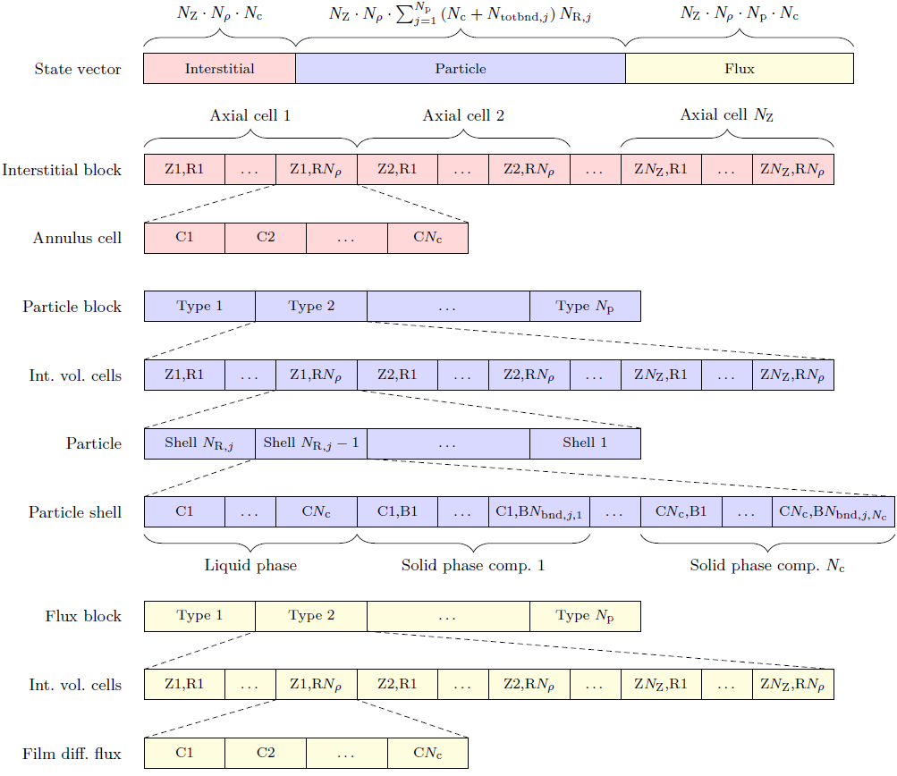
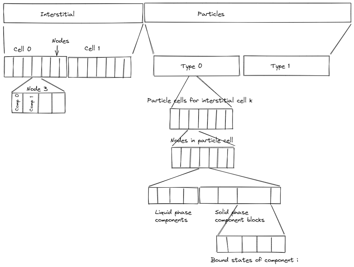
GRM State Ordering (GRM.hpp Line 515-518):

const std::array<StateOrdering, 2> _concentrationOrdering = { { StateOrdering::AxialCell, StateOrdering::Component } };
const std::array<StateOrdering, 4> _particleOrdering = { { StateOrdering::ParticleType, StateOrdering::AxialCell, StateOrdering::ParticleShell, StateOrdering::Component } };
const std::array<StateOrdering, 5> _solidOrdering = { { StateOrdering::ParticleType, StateOrdering::AxialCell, StateOrdering::ParticleShell, StateOrdering::Component, StateOrdering::BoundState } };
const std::array<StateOrdering, 3> _fluxOrdering = { { StateOrdering::ParticleType, StateOrdering::AxialCell, StateOrdering::Component } };

LumpedRateModelwithoutPores State Ordering (Line 356-357):

const std::array<StateOrdering, 2> _concentrationOrdering = { { StateOrdering::AxialCell, StateOrdering::Component } };
const std::array<StateOrdering, 3> _solidOrdering = { { StateOrdering::AxialCell, StateOrdering::Component, StateOrdering::BoundState } };

LumpedRatewithPores State Ordering (Line 443-447):

const std::array<StateOrdering, 2> _concentrationOrdering = { { StateOrdering::AxialCell, StateOrdering::Component } };
const std::array<StateOrdering, 3> _particleOrdering = { { StateOrdering::ParticleType, StateOrdering::AxialCell, StateOrdering::Component } };
const std::array<StateOrdering, 4> _solidOrdering = { { StateOrdering::ParticleType, StateOrdering::AxialCell, StateOrdering::Component, StateOrdering::BoundState } };
const std::array<StateOrdering, 3> _fluxOrdering = { { StateOrdering::ParticleType, StateOrdering::AxialCell, StateOrdering::Component } };

GRM2D State Ordering (Line 500-503):

const std::array<StateOrdering, 3> _concentrationOrdering = { { StateOrdering::AxialCell, StateOrdering::RadialCell, StateOrdering::Component } };
const std::array<StateOrdering, 5> _particleOrdering = { { StateOrdering::ParticleType, StateOrdering::AxialCell, StateOrdering::RadialCell, StateOrdering::ParticleShell, StateOrdering::Component } };
const std::array<StateOrdering, 6> _solidOrdering = { { StateOrdering::ParticleType, StateOrdering::AxialCell, StateOrdering::RadialCell, StateOrdering::ParticleShell, StateOrdering::Component, StateOrdering::BoundState } };
const std::array<StateOrdering, 4> _fluxOrdering = { { StateOrdering::ParticleType, StateOrdering::AxialCell, StateOrdering::RadialCell, StateOrdering::Component } };

CSTR State Ordering (Line 256-257):

const std::array<StateOrdering, 1> _concentrationOrdering = { { StateOrdering::Component } };
const std::array<StateOrdering, 3> _solidOrdering = { { StateOrdering::ParticleType, StateOrdering::Component, StateOrdering::BoundState } };

After looking at this I think if we put a few restrictions on CADET and the interface we can make this work pretty cleanly.

For CADET we need a restriction that the order of the output must be the same for all unit operations. An output dimension can be missing but the order must be the same. This is true for all the existing items and simplifies the interface.

In the interface if a dimension is missing instead of handing a number back it could hand a 0. This would allow the interface to know exactly what the dimensions of the system are and also know what each dimension is.

Based on the current interface for getting the outlet this is what I propose for some of the other return data types and this pattern can be followed for the rest

cdtResult getSolutionOutlet(cdtDriver* drv, int unitOpId, double const** time, double const** data, int* nTime, int* nPort, int* nComp)

would lead to

cdtResult getSolutionInlet(cdtDriver* drv, int unitOpId, double const** time, double const** data, int* nTime, int* nPort, int* nComp)

cdtResult getSolutionBulk(cdtDriver* drv, int unitOpId, double const** time, double const** data, int* nAxial, int* nRadial, int* nComp)

cdtResult getSolutionParticle(cdtDriver* drv, int unitOpId, double const** time, double const** data, int* nParType, int* nAxial, int* nRadial, int* nShell, int* nComp)

cdtResult getSolutionSolid(cdtDriver* drv, int unitOpId, double const** time, double const** data, int* nParType, int* nAxial, int* nRadial, int* nShell, int* nComp, int* nBound)

cdtResult getSolutionFlux(cdtDriver* drv, int unitOpId, double const** time, double const** data, int* nParType, int* nAxial, int* nRadial, int* nComp)

cdtResult getVolume(cdtDriver* drv, int unitOpId, double const** time, double const** data)
1 Like

@s.leweke, do you see any issues with this approach or are we missing something? Could we generally enforce this behaviour even with newer unit operations that might have a different internal structure (e.g. DG/filtration/centrifugation) or would we make our lives too complicated further down the line?

This is a diagram of the state vector structure of the 2D GRM. The 1D GRM does not have the annulus cells (no radial zones). In addition, the lumped rate model with pores only has a single particle shell. The lumped rate model without pores looks quite different, as well as the CSTR.

The solution recorder implementation (include/common/SolutionRecorderImpl.hpp) basically copies the internal state vector data into a large array. For each timestep, the data is appended:

  • The interstitial part is appended as is.
  • The particle liquid phase is copied from the state vector (skipping the solid phase entries) and appended.
  • The particle solid phase is copied from the state vector (skipping the liquid phase entries) and appended.
  • The flux is appende as is.

The exported data (written to file or queried from C interface) is taken from the buffers of the solution recorder. That is, the data pointer will be set to the buffer such that no copy occurs. This requires that the order of the data in the internal buffer is always the same.

As of now, the order is essentially the same for all unit operations. However, we cannot guarantee that this will hold true forever. The order for the DG unit may already be different!

However, this could be fixed by making the solution recorder responsible for maintaining the same order for its internal buffers. This may incur additional costs for reordering (instead of simply copying).

Another point: I’d suggest to add functions to retrieve the coordinates. Maybe also remove the time pointer from all the signatures (but for inlet and outlet) and add a separate getSolutionTimes() function. This is a matter of taste, though.

Thanks a lot for this overview. @j.breuer can you please add how this would look like for DG!?

The DG state vector will be similar but for each cell we will have N_n nodes. So in the above scheme you can think of an additional layer in between the cell level and the next level or you can just think of it as the number of discrete points and substitue cells with nodes. So instead of having N_z discrete points (e.g. cells) we will have N_z \cdot N_n discrete points (e.g. nodes). This way the above scheme doesnt change, only the number of discrete points changes.

@j.breuer: How the state vector is organized is entirely your choice. There are a lot of possibilities.
My take for the 1D GRM would be:

Of course, I’d suggest to first do only one particle type and exactly 1 bound state per component.

1 Like

Another idea: Reverse the responsibilities.
Instead of the SolutionRecorder digging out the parts of the unit’s state vector based on its description, have the unit do the heavy lifting itself. That is, the unit gets handed a memory buffer and needs to write the requested parts of its state vector into the buffer, but in a globally standardized format. This would require:

  • Units need to expose the amount of storage / elements for their state vector parts (e.g., how many elements does the interstitial phase of one component take up).
  • Units expose methods to store their internal state parts in a standardized format into a given memory buffer.

In my view, this would be a cleaner / more extensible architecture. Take this as an RFC (comments and ideas are welcome).

Going with this idea of imposing a certain output buffer format on the unit operations, how should that look like?

  • Volume data: Easy, just a scalar value for each time point.
  • Inlet and outlet: Two options here.
    • Time-major: Time, component
    [time0comp0, time0comp1, time1comp0, time1comp1, ...]
    
    • Component-major: Component, time
    [comp0time0, comp0time1, comp0time2, ..., comp1time0, comp1time1, comp1time2, ...]
    
  • Column bulk: Similarly, several options due to combinatorial explosion. I only list options I deem reasonable.
    • Time, (radial position), axial position, component
    • Component, time, (radial position), axial position
    • Time, component, (radial position), axial position
  • Particle liquid phase:
    • Time, (radial position), axial position, particle type, particle shell, component
    • Component, time, (radial position), axial position, particle type, particle shell
    • Time, component, (radial position), axial position, particle type, particle shell
    • Component, particle type, time, (radial position), axial position, particle shell
    • Particle type, component, time, (radial position), axial position, particle shell
    • Time, particle type, component, (radial position), axial position, particle shell
    • Time, component, particle type, (radial position), axial position, particle shell
  • Particle solid phase: Same as particle liquid phase.
  • Column bulk-particle-flux:
    • Time, (radial position), axial position, particle type, component
    • Time, (radial position), axial position, component, particle type
    • Component, time, (radial position), axial position, particle type
    • Time, component, particle type, (radial position), axial position
    • Time, particle type, component, (radial position), axial position
    • Time, particle type, (radial position), axial position, component

I’d suggest the first choice for every field, because this is precisely the state vector ordering for the finite-volume-based models and, hence, incurs the least costs for copying the data into the buffer every time step(!). I’d rather prefer fast simulation and a little more costly post-processing (e.g., plotting) than a little slower simulation and a little faster post-processing. But I’m open to be convinced otherwise.

Opinions / votes?

From my experience there, time-major makes sense.

Actually, it’s not quite the same since it also depends on the number of bound states.

Just dropping in a reference to my recent developments in CADET-Process/ModelBuilder.

Currently, this only reads the output file but this should also be able to later use the in memory interface. For all types of solutions, there is a class which gets the information about its expected dimensionality in the constructor, as well as the required coordinates. It then provides convenient methods for plotting (1D, 2D) and animating the solution. The class is used for process evaluation (stationarity/fractionation). In future, I also plan on adding methods to interpolate the signal. Furthermore, it might make sense to also store the volumetric flow rates for each of the solution objects in order to account to actual mass that is being transported/accumulated.

The convention we decide on here should hold for both file- and memory-based interfaces.

Yes, we should do that. How should that look like?

  • Volumetric flow rate over time for each unit operation’s inlet and outlet ports?
  • A complete connection matrix (inlet ports are rows, outlet ports are columns; all unit operations are considered) for each time point?

The first choice only records how much went into a unit and how much went out. The second choice also records from where it came and where it went.

Besides, I don’t see a clear vote for one of the orderings, @j.schmoelder. Is this on purpose?

Generally, I always prefer having everything on unit operation level since it makes it much easier to handle. But saving the information about the connectivity is equally important.
Again, both of these features are already implemented in CADET-Process. For the Process class, there are these things called TimeLine (feel free to suggest another name) which store the state of any section dependent input parameter. This includes flow rates, so for every unit operation, the total (internal) flow rate is stored, as well as the outgoing flow rates per “destination” (see the general FlowSheet concept of CADET-Process).

I do think that some of these features should eventually be moved a level down to the ‘Core’ but I can also encourage everyone to start using CADET-Process! :wink:

I should have been more clear. I vote for how it’s generally already implemented, i.e.

Time, (radial position), (axial position), (particle type), (particle shell), (bound_state), component

One thing we could discuss is how dimensions and coordinates are dropped. E.g. a GRM is equivalent to a 2D-GRM with just one radial position. The difference in the solution however is that the GRM does not “contain” that radial dimension, whereas a 2D-GRM with one radial position would have one entry there. I tried using the coordinates to determine the dimensionality of the solution, however, the single radial coordinate is present for both cases in the /output/coordinates branch which required some additional checks when implementing the solution classes.
It’s not really important, just something that I noticed.

We / you should! But this is independent from this discussion.
Having this information available in the high-level frontend is certainly really nice. Nevertheless, I think there might be value in recording what actually got simulated. What you think would happen might not be what actually happened (because of bugs in core, frontend, or for whatever reason).

Maybe save only incoming and outgoing flow rates per port as of now (omitting connectivity info)? That would be fairly simple to implement.

I see what you mean. The HDF5 multi-dimensional arrays support singleton dimensions (as they’re called in numpy / Matlab). From the in-memory interface, you would only get a pointer to a buffer holding the linearized array data. In addition, you would get the dimensions / shape. So the same problem might apply here.

Do you have suggestions or should we ignore this for now?

I would prefer we keep the same order that we already have now so that the file format remains the same. If we change the order from what it is now then anything that reads from hdf5 will have to be changed and have to check the version to change how it reads.

We had another short discussion today and were wondering if this should rather be

Time, (radial position), axial position, particle type, component

Yes, you’re right. I’ll correct the post above. Thanks for spotting this.